Volume I 4. STORE ACCESS CONTROL 4.1 Need for Store Access Control 4.2 Units which require Access 4.3 Relative Access Requirements of the Different Units 4.4 Store Access Priority 4.5 Parity Checks 4.6 Capacity of Store Access Control Unit 5. COORDINATOR AND INSTRUCTIONS 5.1 Introduction 5.2 Registers of the Coordinator 5.3 Form of Instruction 5.4 Discriminant 5.5 Modification 5.6 Carrying out an Instruction 5.7 Selecting the next Instruction 5.8 Conditions affecting the execution of an Instruction 6. ARITHMETIC 6.1 Introduction 6.2 The Arithmetic Unit - LEO III 6.3 The Arithmetic Unit - LEO 326 5.4 System of Arithmetic 6.5 Overflow - LEO III 6.6 Overflow - LEO 326 6.7 Arithmetic Actions 7. FLOATING POINT AND DOUBLE LENGTH ARITHMETIC 7.1 Floating Point Arithmetic 7.2 Double Length Arithmetic Amendment No. 8 December 1964
Volume I 8. SEQUENCE CHANGING AND MODIFICATION 8.1 Sequence Changing 8.2 Subroutines 8.3 Direct Modification 8.4 Indirect Modification 8.5 Multiple Modification 9. INPUT AND OUTPUT GENERAL 9.1 Introduction 9.2 Assemblers 10. INPUT EQUIPMENT 10.1 Elliott Paper Tape Reader 10.2 Elliott Punched Card Reader 10.3 I.C.T. Punched Card Reader 10.4 24-hour Clock 10.5 Millisecond Timer 10.6 Burroughs Punched Card Reader 10.7 Leo-Parnall AUTOLECTOR On-Line Document Reader 11. PUNCHED CARD/PAPER TAPE INPUT ASSEMBLER 11.1 Media and Routes 11.2 Computer Control 11.3 Checks 11.4 Storage of Information 11.5 Non-Standard Paper Tape 11.6 Non-Standard Cards 12. MAGNETIC TAPE EQUIPMENT 12.1 Magnetic Tape 12.2 Ampex Magnetic Tape Decks Amendment No. 8 December 1964
Volume I 13. MAGNETIC TAPE ASSEMBLER 13.1 Medium and Routes 13.2 Computer Control 13.3 Storage of Information 13.4 Lockout 13.5 Warning of End 13.6 Checks 14. OUTPUT EQUIPMENT 14.1 Teletype Paper Tape Punch 14.2 I.C.T. Card Punch 14.3 Anelex 56-160 Line Printer 14.4 Anelex Series 4 Line Printer 14.5 I.B.M. Output Writer 15. OUTPUT ASSEMBLERS 15.1 Paper Tape Punch Assembler 15.2 Special Anelex Printer Assembler 15.3 General Purpose Output Assembler 15.4 Standard Anelex Printer Assembler 16. DATA HANDLING ACTIONS 16.1 File Control 16.2 Handling Input Data 16.3 Preparing Data for Output 16.4 Requirements of the General Purpose Output Assembler 16.5 Data held in Integral Word form 16.6 Sorting
Volume I 17. FACILITIES FOR CONCURRENT RUNNING OF PROGRAMMES 17.1 Interruption 17.2 Store Reservation and Lockout 17.3 Communication with the Operator 17.4 Halting the Computer APPENDICES: A. Character Codes B. Concise Instruction Code C. Operators Controls and Indicators D. Sample Computer Code Action Times E. Use of Store Compartments in Division 0 F. Transfer Rates for Anelex Printers and Ampex Tape Decks
Section 1 1. CONCEPT OF THE COMPUTER 1.1 General Features of any Computer In order to carry out the processing of data, any computer requires the following basic units: (i) An Input Unit to provide the computer with data from some external medium such as paper tape. (ii) A memory or Store to enable the computer to hold information. (iii) An Arithmetic Unit to enable the computer to carry out calculations on data in the store. (iv) An Output Unit to allow the computer to supply results on some external medium - e.g. printed results. The operation of all these units is controlled, automatically by the Coordinator. This unit gives effect to instructions taken one at a time from a Programme held in the store. The relationship between these units is shown below:

Section 1.2 1.2 Special Features of LEO III and LEO 326/360* Because the operation of input and output equipment is slow compared with calculation processes within the computer, the system is designed to allow input and output to proceed independently of the coordinator. This leaves the coordinator free to carry on with other instructions while input or output is taking place, and allows several input or output devices to work concurrently. This concurrent operation is achieved by the use of devices known as Assemblers, which control the transfer of data to or from the inpu and output equipment to which they are connected. Input or output of a block proceeds under assembler control after initiation by the coordinator. Assemblers and the arithmetic unit need to put data into the store and take it out. Since they work concurrently, several requests for access may occur simultaneously, and some system of store access control is therefore needed. In LEO III, the Store Access Control Unit provides this control, dealing with requests according to priority. In LEO 326* a unit known as the Peripheral Priority Control (PPC) deals with requests for access from assemblers, while the Calculator Priority Control (CPC) deals with requests for access from the PPC and the Arithmetic Unit. * Note: The difference between LEO 326 and LEO 360 lies in their store* speeds. The point is covered in section 3.2, apart from which this volume makes no distinction between the two machines. Amendment No. 8 December 1964
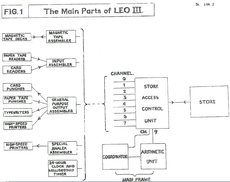
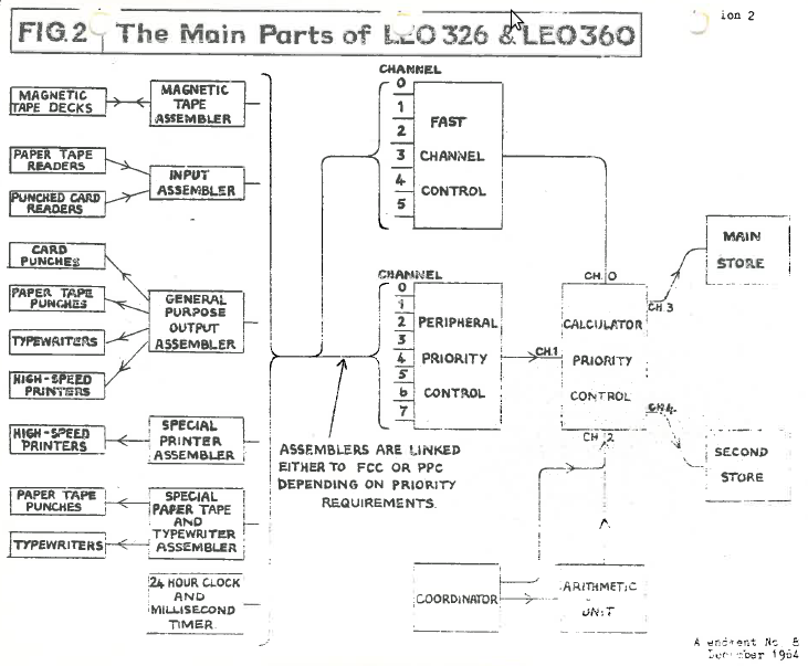
Section 2 2. OUTLINE DESCRIPTION OF MAIN PARTS 2.1 Introduction A LEO III computer consists of the following types of basic unit, each of which has a distinct function to perform: Magnetic core store Store access control unit Arithmetic unit Coordinator Assemblers Input and output equipment The inter-relation between these units is shown in Fig. 1, A LEO 326 computer consists of the following types of basic unit: Magnetic core store Peripheral priority control Calculator priority control Arithmetic unit Coordinator Assemblers Input and output equipment The inter-relation between these units is shorn in Fig. 2. 2.2 Magnetic Core Store A store is built up of compartments, each of which consists of a number of magnetic cores. Compartments are used to hold all types of data - programme and intermediate results as well as input and output data. A more detailed description is given in section 3. LEO 326 may have two stores, referred to as the main store and the second store, although they have the same status. 2.3 Arithmetic Unit This unit contains the registers and logical circuits that are used for arithmetic and other logical operations. The basic circuits operate in binary radix but special facilities are included which permit instructions to be carried out using information held in other radices such as decimal or sterling. The arithmetic unit operates on digits each comprising a quartet of bits, which may be contained in either long words of 40 bits and sign or short words of 20 bits and sign. Amendment No. 8 December 1964
Section 2.4 2.4 Coordinator This unit directs the execution of instructions. It selects instructions one at a time - normally in the order in which they are held in the store, interprets the instruction and initiates the proper signals to other units concerned. It gives effect to an instruction by executing a routine of 'micro- actions', which control the basic circuits in the arithmetic unit. The routines are built into core matrices in the coordinator. The coordinator and arithmetic unit are described in section 5. 2.5 Input and Output Equipment These devices are provided to read information from, or to record it on, external media. They include: Paper tape readers Punched card readers Magnetic tape decks Paper tape punches Card punches Line printers Typewriters Clocks They are sometimes referred to collectively as 'peripheral equipment'. They are described in sections 9 to 15. 2.6 Assemblers An assembler is a unit which links input and output equipment to the store via the store access control. Different types are required for different kinds of input/output equipment, but, one assembler can be linked to several devices and operate them one at a time as required. An assembler either receives data from the store in a standard form and converts it into the particular form required by the output device, or performs the reverse transformation for input. Assemblers and input/output equipment are described in sections 9 to 15. Amendment No. 8 December 1964
Section 2.7 2.7 Store Access Control Access to the store can only be given to one channel at a time. Since several requests for access may occur simultaneously, a priority system is necessary. In LEO III, this is provided by the Store Access Control Unit, which accepts calls for access from the channels connected to it (8 assemblers and the arithmetic unit) and decides between competing calls on the basis of fired channel-priorities. Priority numbers are arranged in such a way as to ensure that, although some channels may have to wait from time to time, the delays do not cause any corruption of information. The Store Access Control Unit (SACU) is described in detail in section 4. In LEO 326, the control system is distributed between two units, one subordinate to the ether. A unit known as the Peripheral Priority Control (PPC) deals directly with assemblers; having decided between any competing requests, the PPC passes on the successful request to the Calculator Priority Control (CPC). This unit controls transfer of data along three channels - those linking the stores to the PPC, the calculator, and the Fast Channel Control (FCC), - an optional extra that provides direct connection between the CPC and high-speed peripheral devices. 2.8 External Controls The operators' panel contains the basic controls necessary for efficient operation of the computer, together with some monitoring facilities, including warming lamps for all major classes of computer fault. The engineers' panel contains all the computer controls and monitoring facilities except those peculiar to assemblers and peripheral equipment; it provides controls and facilities for testing and investi- gation of faults. Amendment No. 8 December 1964
Section 3 3. STORAGE AND FORM OF INFORMATION 3.1 Introduction All information in the computer is represented by patterns of bits. Each bit can take the value 1 or 0, and is represented by: (a) The presence or absence of a pulse on a wire, during transfer of information. (b) The state of one of a variety of two-state devices. The computer store uses toroidal magnetic cores which can be magnetised in either of two directions. The registers use electronic circuits known as 'flip-flops', which can be in one of two states, 'set' or 'reset'. For calculation purposes, numbers are usually held as quartets of bits, each of which represents a digit in come particular numerical system (decimal, sterling, etc). Alphabetic characters are held as octets of bits. Numeric characters are also held as octets for purposes of input and output. Characters held as octets are usually referred to as 'alpha/numeric' characters, or as being held in 'alpha form'. These representations are described in detail in sections 3.3 to 3.5 inclusive, 3.2 The Store A block of magnetic core store in a LEO III/326 computer consists of up to'four 'divisions', each composed normally of 4096 'long compartments' used to hold 'words' of information. Smaller divisions are available comprising 1024, 2048, or 3072 long compartments. LEO III normally has one block of storage, with a cycle time of approximately 14 microseconds. The LEO 326 store comprises one block with a store cycle time of 2½ microseconds, and an optional second block with a store cycle time of either 2½ or 6 microseconds. LEO 360 has one or two blocks of store, each with a cycle time of 6 microseconds. In LEO 326 and 360 the two stores are known as the Main Store and the Second Store, although they have the same status and may be accessed simultaneously. Each long compartment is divided into two adjacent 'short compartments' which are able to hold 'short words' of information. The short compartments in a division are numbered from 0 to 8191; in instructions this number is used to address the compartment, a long compartment being addressed by the number of its even (first) short compartment. In this manual a long compartment is referred to with an apostrophe following its address (e.g. 2p') to distinguish it from the corresponding short compartment 2p. Amendment No. 8 December 1964
Section 3.3 Each long compartment consists of 44 or 48 bits, each of which is represented by a magnetic core. The bits are numbered as follows: _________________________________________________________________________ |Opt.| | | | | | | | | | | | | | | |Tag | | | B | B | B | B | B | | | B | B | B | B | B | |4 |P2|S2|40-37|36-33|32-29|28-25|24-21|P1|S1|20-17|16-13|12-9|8-5 |4-1 | |Bits| | |(Q10)| (Q9)| (Q8)| (Q7)| (Q6)| | | (Q5)| (Q4)|(Q3)|(Q2)|(Q1)| More sig. Long compartment 2p' Less sig. end end OR _________________________________________________________________________ |Opt.| | | | | | | | | | | | | | | |Tag | | | B | B | B | B | B | | | B | B | B | B | B | |4 |P2|S2|20-17|16-13| 12-9| 8-5 | 4-1 |P1|S1|20-17|16-13|12-9|8-5 |4-1 | |Bits| | | (Q5)| (Q4)| (Q3)| (Q2)| (Q1)| | | (Q5)| (Q4)|(Q3)|(Q2)|(Q1)| Short compartment 2p+1 Short compartment 2p The 4-bit tag of each long compartment is used in conjunction with the optional* store reservation system (see section 3.10). Pn are parity bits used for checking accuracy of information and are described in section 3.9. Sn are sign bits used to indicate the sign of a number and are described in section 3.7. (Note: That when a compartment is being used as a long compartment the value of Si is ignored). Qn are quartets of bits used to hold information. 3.3 Numeric Form This is the form in which numbers are normally held for calculation purposes. A quartet of bits can be used to hold one digit of a number in any radix (including mixed radices such as Sterling) provided that the radix is such that no digit position has a maximum value greater than 15. The digits are held in a binary coded form in the quartets; thus the number '23' in decimal should be: 0010 0011 (2) (3) The amount £2-17-11d in sterling would be: 0010 0001 0111 1011 (2) (1) (7) (11) * standard on LEO 326 Amendment No. 8 December 1964
Section 3.4 Note that here only one digit need be used for the pence, since this has a maximum value 11 (written thus to avoid confusion with 11, decimal, which is represented as 0001 , 0001). Two digits must, however, be used for the shillings, since the largest number which can be held in one quartet is 15. A long compartment can hold 10 digits and sign in numeric form, and a short compartment 5 digits and sign. Numbers are held aligned to the least significant end of a compartment. 3.4 Binary Form Numbers may be held in bits 1 to 20 and S of a short compartment, or bits 1 to 40 and S2 of a long compartment, in binary notation. In this notation bit 1 has a value 20, bit 2 a value 21, bit 3 a value 22 and so on. Thus the decimal number '23' in binary notation would be: 10111 Binary form can be regarded as radix 16 in numeric form, i.e each quartet has a maximum value of 15. 3.5 Alpha Form Alphanumeric characters are held in this form. Each character occupies two adjacent quartets in a long compartment, i.e. either Q1 and Q2, Q3 and Q4, Q5 and Q6, Q7 and Q8 or Q9 and Q10, but not such pairs as Q2 and Q3, Q4 and Q5, etc. The more significant quartet of the character is known as the control quartet, the less.significant quartet as the basic quartet. The value of these quartets for any character is given in Appendix A, The alpha code is so arranged that alphabetic precedence can be determined by subtraction, e.g. ___________________ JONES is represented as |6|1|6|6|6|5|5|5|7|2| ___________________ JONAS is represented as |6|1|6|6|6|5|5|1|7|2| JONAS is numerically less than JONES, and hence precedes JONES. The arithmetic actions are primarily designed to operate on words in numeric form; :thus arithmetic will not normally be performed on alpha items, except to establish precedence as in the above case. A long compartment can hold 5 characters in alpha form. The sign bits S1 and S2 are not used. Information in alpha form is not usually held in short compartments, although two characters may be held in a short compartment if necessary (in this case they are held in Q1 and Q2, Q3 and Q4). Amendment No. 8 December 1964
Section 3.6 3.6 Instruction Form Computer instructions may be held in bits 1 to 20 and S of a short compartment as described in section 5.3. 3.7 Signs The sign of a number in binary or numeric form is represented by the sign bit of the short compartment, or the sign bit S2 of the long compartment which contains the number. The sign bit is set at 1 for a negative number or at 0 for a positive number. Numbers are held in the store in sign and modulus form, e.g. in decimal: ______________________________________ + 16 is held | 0 | 0000 | 0000 | 0000 | 0001 | 0110 | ______________________________________ - 24 is held | 1 | 0000 | 0000 | 0000 | 0010 | 0100 | S Q5 Q4 Q3 Q2 Q1 Negative numbers in the arithmetic unit are usually held in sign and complement form (see section 6). 3.8 Transfer of Information to and from Assemblers All transfers between the assemblers and the store are in words of five alpha characters. Transfers between the assemblers and the peripheral equipment are usually in c)characters of six bits - the six least significant bits a of the octet pattern. 3.9 Parity Bits When a word is placed into the store, the parity bit of each short compartment involved is set at 1 if necessary to make the total number of bits with value 1 in the short compartment (including sign and parity) an odd number. This parity bit is inserted by the store access control unit (see section 4). Information taken from the store is checked by store access control and if found to be incorrect (i.e. if either short word contains an even number of bits with value 1) the computer stops immediately. The address of the offending compartment is displayed on the engineers' control panel. (For LEO 326, read 'CPC' for 'SACU' in this section). Amendment No. 8 December 1964
Section 3.10 3.10 Store Reservations This is an optional facility provided to safeguard the operation of the computer when more than one programme is held in the store at the same time. Each long compartment has a 4-bit tag used to hold a number which identifies the programme associated with it. If any other programme tries to use store space associated. with this programme, a 'lockout' occurs, causing the computer to stop immediately. The system is described in detail in section 16, 3.11 Special Compartments of the Store The first-160 compartments in division 0 of the store are used for special purposes - a full list is given in Appendix E. Amendment No. 8 December 1964